Electrical Physics
IN THIS LESSON
Understand the basic components of a circuit and how to solve for them using Ohm’s Law.
10/6/25: Welcome to the Electrical section of the Physics course! This chapter will be based on the AP Physics C: Electricity & Magnetism course or the typical second physics course at a university and some basics of electrical engineering.
I will be formatting this the same way I formatted the kinematics lesson. I will still have the PDF version of this lesson attached at the bottom of the page.
Electric circuits are one of the most fundamental topics in physics and electrical engineering. Their most basic relevant quantities are voltage, current, and resistance, which are all conveniently related through Ohm’s Law. In this lesson, we will gain a basic understanding of circuit diagrams, these core quantities, and how to solve for them (i.e. "solve a circuit") using Kirchhoff's Laws and Ohm's Law.
Before we begin solving for real values, we need to understand how to look at a circuit diagram, called a schematic and understand what is happening. The most commonly used schematic symbols are:
The following image will give a visual of these schematic symbols.
Before we begin solving for real values, we need to understand how to look at a circuit diagram, called a schematic and understand what is happening. The most commonly used schematic symbols are:
- Batteries/Voltage Sources: In more basic or simple circuits, a battery may be represented by two parallel lines that are both perpendicular to the circuit wires with a gap in between them, with one line being longer to represent the positive terminal of the battery. This is the terminal or "end" of the battery that the current "flows" out of (we will discuss the intricacies of current in a later lesson). In a more complex circuit or in a more advanced setting, a constant voltage source, such as a battery, may be represented by a circle with a + and a - sign to indicate which terminals are positive and negative. (There is also such thing as a variable or dependent voltage source, but we will not address that for a while.)
- Current Sources: In a more complex circuit, a constant current source may be represented by a circle with an arrow inside indicating which way the current is flowing. We will not be using current sources in our lessons for some time.
- Resistors: A resistor is an element of a circuit that impedes current flow. They are very important in most circuits as they prevent the battery from burning out from its own voltage. They are represented by a small zig-zag shape within a wire. They may have more zig-zags based on how high their resistance is, but this is not always the case.
The following image will give a visual of these schematic symbols.
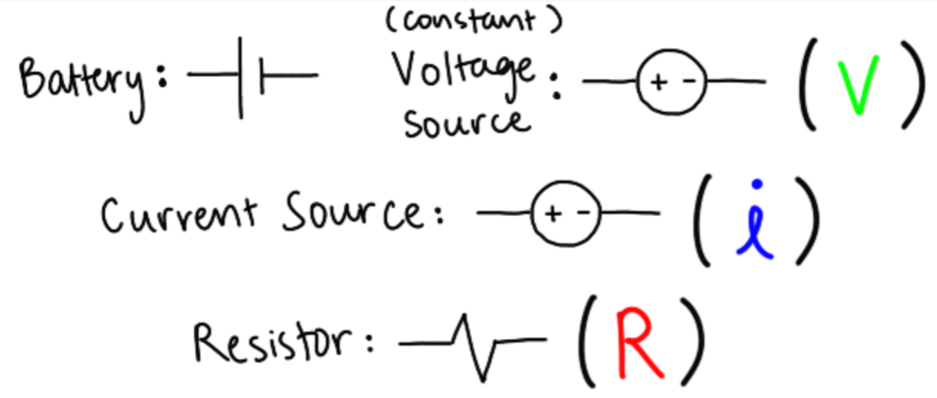
Image showing the schematic symbols for batteries, constant voltage sources, constant current sources, and resistors.
You can see in the above diagram that I've written some variable labels in parentheses. These are the quantities relevant to each circuit element that we will be working with in this lesson and in the future.
These three core quantities are related by Ohm's Law, 𝑉 = 𝑖𝑅.
- Voltage (𝑉): The difference in electric potential between two points in a circuit. Electrical potential is the amount of work done by an electric charge, or work per charge. Voltage is measured in volts (V).
- Current (𝑖): The flow of electric charge or electrons through a wire. Current is measured in amperes (A).
- Resistance (𝑅): How strongly a circuit element, often a resistor, impedes the flow of current in a circuit. Measured in ohms (Ω).
These three core quantities are related by Ohm's Law, 𝑉 = 𝑖𝑅.

Schematic of the most basic circuit consisting of only a battery and a resistor, depicting the core quantities of voltage, current, and resistance.
Noticing the way circuit elements are connected is very important to solving them. There are some specific terms that we can use to describe connections in a circuit that will simplify our circuit-solving process.
Current splits at nodes, making current in parallel resistors different from the current leading into them, but keeping the voltage the same. Voltage drops by some amount at each resistor in series, but the current in resistors in series are all equal.
- Nodes: A node is where two wires of a circuit meet, often in a 'T' shape.
- Series Connections: Two circuit elements are in series when they are on the same single wire, connected end-to-end.
- Parallel Connections: Two circuit elements are in parallel when they are on two different wires or 'branches' across the same two nodes.
Current splits at nodes, making current in parallel resistors different from the current leading into them, but keeping the voltage the same. Voltage drops by some amount at each resistor in series, but the current in resistors in series are all equal.
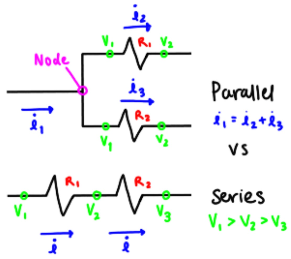
Schematics depicting series and parallel connections. Voltage drops are depicted as voltages at nodes indicating that the voltage has decreased since the last node due to the current passing through a resistor.
A quick and related concept to resistors in series and parallel is equivalent resistance. This is the concept that all resistors in a circuit can be replaced with one resistor with equivalent resistance to the original combination of resistors.
Resistors connected in series with each other can be simplified to one resistor with resistance equal to the sum of the resistances of the original resistors. That is, 𝑅eq = 𝑅1 + 𝑅2 + ... + 𝑅n.
Resistors connected in parallel with each other can be simplified using the following equation (any attempt to explain with words would be way more confusing): 1/𝑅eq = 1/𝑅1 + 1/𝑅2 + ... + 1/𝑅n.
You can use these equations over and over again and switch between the two when needed when solving circuits that have combinations of series and parallel connections.

Schematics depicting series and parallel resistors and how to find their equivalent resistance. (Apologies for the resolution on this image; I don’t know why it’s suddenly so poor.)
Finally, the last things to know before we learn the process of solving a circuit are Kirchhoff's Voltage and Current Laws.
Note: It's hinted at here and something that will become far more important later, but there is a sign convention for positive and negative voltage and current. Generally, a voltage or current is considered positive when the current or current related to the voltage is leaving the negative end of the element, such as the negative terminal of a battery or the "negative end" of a resistor. When it comes to resistors, you can define the positive end as the end closest to the positive terminal of the voltage source or current source and the negative end as the end closest to the negative terminal of the power source. There were quotation marks earlier because there is no inherent positive or negative ends of resistors. You will only need this knowledge in future lessons.
- Kirchhoff's Voltage Law (KVL): KVL states that the voltage of a loop should be equal to 0. This is to say that given a loop, or a closed section of the circuit that can be traced in one line from the positive terminal of a battery to the negative terminal, the total voltage drops in the loop should add up to the voltage of the battery, or 𝑉bat.
- Kirchhoff's Current Law (KCL): KCL states that all the total current at a node should be equal to 0. This is more easily understandable and harder to mess up when defined as the statement that the total current going into a node should equal the total current leaving the node, or that 𝑖in = 𝑖out.
Note: It's hinted at here and something that will become far more important later, but there is a sign convention for positive and negative voltage and current. Generally, a voltage or current is considered positive when the current or current related to the voltage is leaving the negative end of the element, such as the negative terminal of a battery or the "negative end" of a resistor. When it comes to resistors, you can define the positive end as the end closest to the positive terminal of the voltage source or current source and the negative end as the end closest to the negative terminal of the power source. There were quotation marks earlier because there is no inherent positive or negative ends of resistors. You will only need this knowledge in future lessons.

Diagram demonstrating visually how Kirchhoff’s Voltage Law and Kirchhoff’s Current Law work.
We usually stick to conceptual explanations on STEM+, but this concept is quite difficult to understand without first applying it to some examples. So, with this understanding, let's begin to solve some resistor-only circuits!
Note: We're going to switch between using the battery and constant voltage source schematic symbols to get you used to both.
Here is the simplest possible example:
Note: We're going to switch between using the battery and constant voltage source schematic symbols to get you used to both.
Here is the simplest possible example:

This example only involves one resistor and one power source, making it the simplest application for Ohm's Law.
The work to complete this problem goes as follows:
Applying Ohm's Law: 𝑉 = 𝑖𝑅
Solve the equation around to find what 𝑅 equals: 𝑅 = 𝑉/𝑖
Plug in the values for 𝑉 and 𝑖: 𝑅 = (12 V)/(4.0 A) = 3 Ω
The resistance 𝑅 of the resistor is equal to 3 Ω.
Let's move onto a (very) slightly more complicated example.

This problem is very similar to the last, but it also applies Kirchhoff's Voltage Law at the end.
First, we apply Ohm's Law like the last problem:
𝑉1 = 𝑖𝑅2Ω, 𝑉2 = 𝑖𝑅5Ω
Then, plug in the values:
𝑉1 = (3.0 A)(2 Ω) = 6 V
𝑉2 = (3.0 A)(5 Ω) = 15 V
We're able to use the same current value for both resistors because they are in series.
Now, we're going to use Kirchhoff's Voltage Law to find the voltage of the battery.
𝑉bat = 𝑉1 + 𝑉2
Now, plug in the values:
𝑉bat = 6 V + 15 V = 21 V
Wasn't that simple!
Our next and last example will be the most complicated, and is here to try and get you to understand how to work your way through a problem even when it's not super clear.

This problem could be solved in a few ways, but this is the method I'm going to use:
First, let's establish some equations using Kirchhoff's Voltage Law:
Loop 1: 10 = 𝑉3Ω + 𝑉2Ω
Loop 2: 10 = 𝑉3Ω + 𝑉4Ω
Replace the unknown voltages with expressions using Ohm's Law:
10 = 3𝑖1 + 2𝑖2
10 = 3𝑖1 + 4𝑖3
Let's establish a third equation using Kirchhoff's Current Law:
Note: To find the value of three unknowns, you need a system of three equations. This applies to any number of unknown variables.
𝑖1 = 𝑖2 + 𝑖3
Let's replace 𝑖1 with 𝑖2 + 𝑖3 in the KVL equations:
10 = 3(𝑖2 + 𝑖3) + 2𝑖2
10 = 3(𝑖2 + 𝑖3) + 4𝑖3
Use the distributive, commutative, and transitive properties to combine these two equations:
10 = 3𝑖2 + 3𝑖3 + 2𝑖2
10 = 3𝑖2 + 3𝑖3 + 4𝑖3
3𝑖2 + 3𝑖3 + 2𝑖2 = 10
3𝑖2 + 3𝑖3 + 2𝑖2 = 3𝑖2 + 3𝑖3 + 4𝑖3
Subtract 3𝑖2 + 3𝑖3 from each side of the equation:
2𝑖2 = 4𝑖3
Divide both sides by 2 to get the following equality: 𝑖2 = 2𝑖3
Replace 𝑖2 with 2𝑖3 in the KCL equation from earlier:
𝑖1 = 2𝑖3 + 𝑖3
Simplify and solve for 𝑖3:
𝑖1 = 3𝑖3
𝑖3 = (1/3)𝑖1
Keep this value in mind! Let's do this same process to solve for 𝑖2:
Replace 𝑖3 with (1/2)𝑖2 in the KCL equation from earlier:
𝑖1 = 𝑖2 + (1/2)𝑖2
Simplify and solve for 𝑖2:
𝑖1 = (3/2)𝑖2
𝑖2 = (2/3)𝑖1
Let's quickly go back and solve for 𝑖1, which we can then plug back into the equalities we've just determined.
Using the first KVL equation and the equality involving 𝑖2 just now, we can find 𝑖1.
10 = 3𝑖1 + 2((2/3)𝑖1)
Simplify:
10 = 3𝑖1 + (4/3)𝑖1 = (13/3)𝑖1
𝑖1 = 2.308
Plug this value of 𝑖1 back into the equalities for 𝑖2 and 𝑖3:
𝑖2 = (2/3)(2.308) = 1.538 A
𝑖3 = (1/3)(2.308) = 0.769 A
We've got all of our values! Let's double-check this using an equation we haven't used in a while.
10 = 3(2.308) + 4(0.769)
This equation is true!
I know this took a long road to get here, but I hope this expresses the logic that you should use when solving circuit problems.
I hope this lesson made circuit problems much simpler to understand!